

A quadcopter, also called a quadrotor, is basically a helicopter with 4 rotors instead of the 2 used in a standard helicopter. Quadcopters have gained tremendous popularity in the field of “Unmanned Autonomous Vehicle (UAV)” research. Quadcopters depend on electronic sensors and control systems to stabilise their flight. The main advantage that a quadcopter has over a helicopter is that since it requires four small rotors, each rotor possesses less kinetic energy and hence will cause less damage if it hits something. Each motor must lift only a quarter of the weight so we can use cheaper motors. Also quadcopters are easier to build and control and due to their small size, can be maneuvered easily in closed spaces too.
MOTIVATION
We realize that the quadcopter is a well-researched topic and models like the one we wish to design have already been implemented. So we intend this project to be solely for educational purposes. We believe that we will gain tremendous knowledge about micro- controller and control systems via this project. We will also learn a lot about flight dynamics and aero-modelling. Last but not the least, it is extremely exciting to build a device that can fly! Also we realise that once the quadcopter has taken flight, there are
a number of uses that we can put it too.
We will discuss the mechanics of flight control. The quadcopter’s movement
is controlled by varying the relative thrusts of each of the 4 rotors. These rotors are aligned
in a diamond. Motors on one diagonal rotate in the clockwise direction and on the other
in the anti-clockwise direction.
• Moving forward
To move forward we reduce the power in the front motor. This tilts the quadcopter
forward and the rotors provide sufficient thrust to move forward. Speed is decided
by the power given to the rotors.
• Moving back
To move backwards we reduce the power in the back rotor, tilting the quadcopter
backwards and then again the thrust from the motors takes it in reverse.
In addition to this, the quadcopter has 3 degrees of freedom namely:
- Yaw
Yaw (turning left and right) is controlled by turning up the speed of the regular
rotating motors and taking away power from the counter rotating; by taking
away the same amount that you put in on the regular rotors produces no
extra lift (it won’t go higher) but since the counter torque is now less, the
quadcopter rotates and control becomes a matter of which motor gets more
power and which one gets less. - Roll
Roll (tilting left and right) is controlled by increasing speed on one motor and
lowering on the opposite one. - Pitch
Pitch (moving up and down, similar to nodding) is controlled the same way
as roll, but using the second set of motors.
Hardware
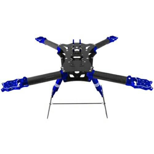
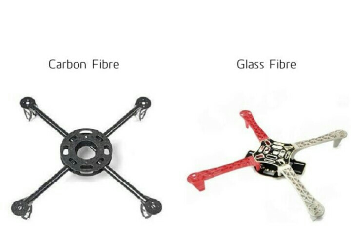
Frame
A frame is a structure that holds all the components together. It should be rigid, and be
able to minimise the vibrations induced by the motors. Our quadcopter frame consists
of three parts:
• The centre plate where the electronics and batteries are mounted
• Four arms connecting to the centre plate
• Four motor brackets attaching the motors to the end of the arms
We have chosen carbon fibre frame since its beginner friendly and due to the small
size of the frame, the cost is also reasonable.
Motors
We have used brushless motors. Ordinary DC motors have coils and magnets which are
used to drive the shaft. They have a brush on the shaft which takes care of switching the
power direction in the coils. Brushless motors don’t have this brush. Instead they have
coils on the inner side (centre) of the motor, which is fixed to the mounting.
On the outer side, they contain a number of magnets mounted to a cylinder that is
attached to the rotating shaft. So, the coils are fixed which means wires can go directly
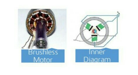
to them and therefore there is no need for a brush. They spin at a much higher speed
and use less power than DC motors (at same speed). Also there is no power loss due to
brush transition. Brushless motors come with a Kv-rating which indicates how many RPMs (Revolutions per minute) the motor will do if provided with V volts under no load. The RPMs can be calculated in this way: RPM=Kv × V We are using 1240 Kv with max power of 150 watts. These motors can provide a thrust of 400 gm at 10 Amps and upto a maximam of 700 gm at 16 Amps. Thrush of about 250 gm (from each motors) would be sufficient for hovering.
Propellers
On each of the brushless motors there is mounted a propeller. In a quadcopter, propellers have opposite tilts. One is for clockwise motion and one for anti-clockwise. This makes the yaw angle stable. Propellers come in various sizes and pitch. We plan to use either 1045 (10 diameter and 4.5 pitch) or 8045 (8 diameter and 4.5 pitch). These are the most commonly used propellers for mid-sized quadcopters.
The diameter gives the area and the pitch gives effective area. With same diameter and larger pitch the propeller would generate more thrust and lift more weight but requires more power. A higher RPM of the propeller gives more speed and manoeuvrability but lifts less amount of weight. The power drawn by the motor increases as the effective area
of the propeller increases. At bigger diameter or higher pitch one will draw more power at the same RPM, but also produces much more thrust and lift more weight. In choosing a balanced motor and propeller combination, you have to figure out what you want your quadcopter to do. If you want to fly around stably with heavy objects like a camera, you would probably use a motor that manages lesser revolutions but can provide more torque and a longer or higher pitched propeller (which uses more torque to move more air in order to create lift). For a quadcopter to fly we need 1:2 ratio for weight and thrust.
Power(watts) = Kp ∗ D4 ∗ P ∗ RPM3
Here D is diameter, P is pitch and Kp for mid sized propellers are around 1.2
http://www.alexandriafranklins360technology.tech.blog
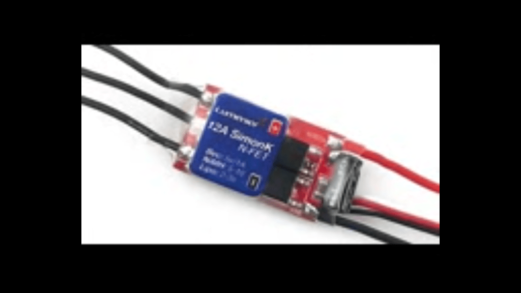
ESC – Electronic Speed Controller
brushless motors are normally 3 phased, so direct supply of DC power will not turn
the motors on. Electronic Speed Controllers generate three high frequency signals, with
different but controllable phases, continuously to keep the motor turning.
ESC has a battery input and a three phase output for the motor. Each ESC is controlled independently by a PPM signal (similar to PWM). The frequency of the signals
vary a lot, but for a Quadcopter it is recommended that the controller should support high frequency signal, so the motor speeds can be adjusted quick enough for optimal stability (i.e. at least 200 Hz or even better 300 Hz PPM signal). We are using 30 Amp ESC with PWM control.
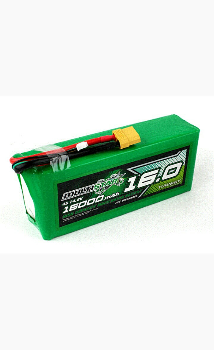
Battery
In Quad rotors, Lithium Polymer (LiPo) Battery is the most commonly used Power
Source because of its light weight and its high current rating. NiMH Battery is a cheaper alternative but is much heavier than LiPo Battery. A single LiPo cell can provide a voltage of upto 3.7 volt.
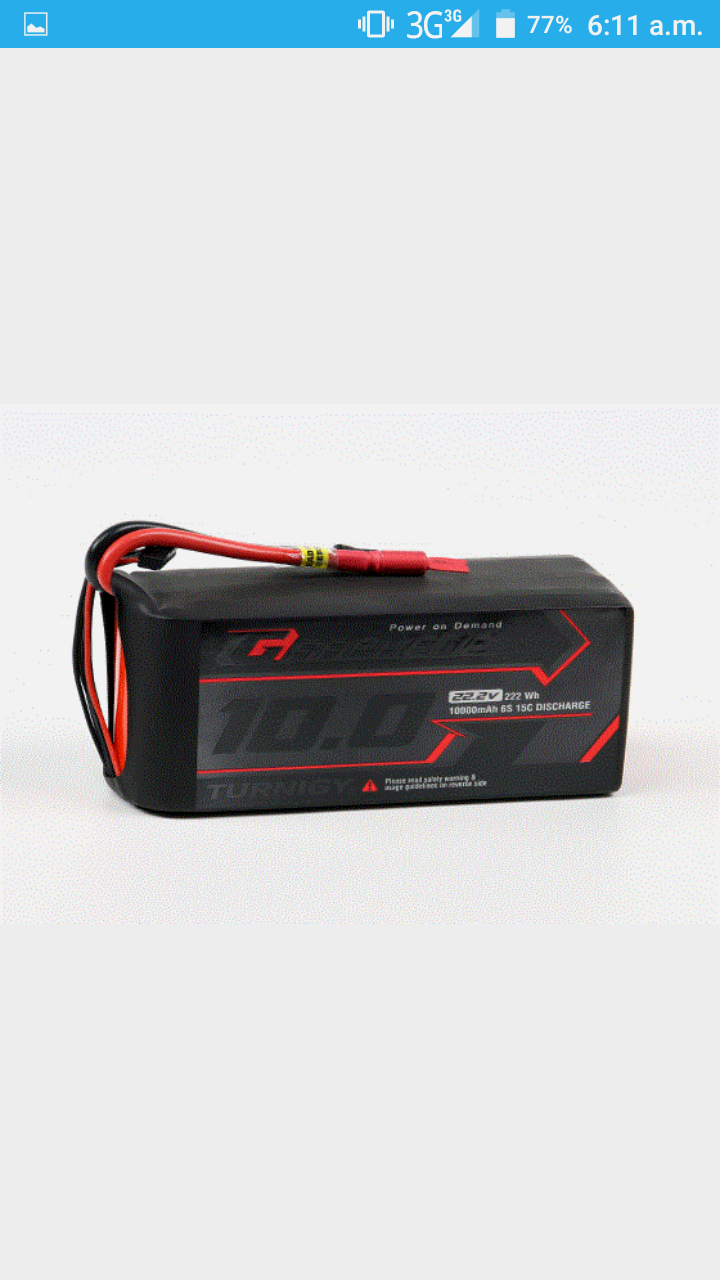
A LiPo battery has two characteristic parameters:
- Capacity
It is measure of how much energy is stored in battery. It is measured in mAh (Amp
hour). A battery with capacity of 4000 mAh can power a 0.8 kg Quad rotor for 5
minutes of full throttle and 20 min of hovering. - Discharge rate
This is the rare at which battery can discharge. It is also called C-rate and expressed
in C units. The maximum current that can be drawn from a battery is simply
product of Discharge rate and Capacity. A 4000mAh 30C 3S LiPo can give up to
120 Amps of maximum current
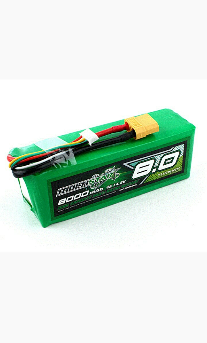
The specifications of the battery we are using are as follows –
Capacity: 4000mAh
Voltage: 3 Cell / 11.1V
Discharge: 25C
IMU (Inertial Measurement Unit)
The IMU is an electronic sensor device which measures the velocity, orientation and
acceleration along different directions. This sensor allows the control system to navigate
the bot in the environment. The readings of the IMU are fed to the main controller
which are then compared with the set points and then appropriate action is taken by the
motor controller system. The IMU is a combination of a 3-axis gyroscope and a 3-axis
accelerometer, which together makes it a 6 degree of freedom sensor. Sometimes a 3-axis
magnetometer is also included to get an absolute yaw control relative to the Earth’s
magnetic field. This makes the IMU a 9 degree of freedom sensor.
COMPONENTS OF THE IMU
Accelerometer
The accelerometer measures the acceleration relative to the gravitational force. So,the 3-axis accelerometer basically gives us components of acceleration in all the 3 directions. It can be used to measure the orientation, vibration and shock and hence is critical for the stability of the Quad copter (in our case). The disadvantage of
only using the accelerometer is that it may become extremely sensitive to unwanted
vibrations and noise (for example motor vibrations) and may lead to instability of
the bot.
Gyroscope
A gyroscope is a device which measures and maintains the orientation based on
the principle of angular momentum. It measures the angular velocity i.e., how
fast something is spinning about an axis as well as rotational acceleration. Unlike
accelerometers gyroscopes are not affected by gravity, so they make a great comple-
ment to each other. Accelerometer measure acceleration along the specified axes
whereas Gyroscopes measure acceleration about the axes.
Magnetometer
A magnetometer measures the strength and the direction of magnetic fields and hence can be used to determine the orientation of the bot with respect to Earth’s magnetic field. This helps in additional Yaw stability.
Interface
Interfacing an IMU is one of the critical tasks since it depends on the availability of
embedded protocols in the respective microcontroller. Most of the IMUs available in the market give output data via an analog, serial or I2C (a multi-master two wire serial bus) interface.
Graphical representation of the output data and trade-offs between the components
of the IMU are shown in
Arduino 10DOF with 3axis Gyro, 3 axis Accel, 3 Axis Compass and
Barometer
We are using a 10 DOF sensor breakout board to make our own IMU. Arduino 10DOF contains ITG-3205 (gyroscope), ADXL345 (accelerometer), HMC5883L(magnetic compass), and BMP085 (Barometer). We have written our own algorithm to get fused data from Arduino 10DOF. We are also using magnetometer for additional yaw stability. Interfacing is done using I2C communications standards with help of wire library on arduino.
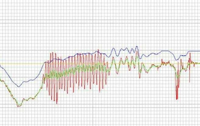
In the above graph, the green line corresponds to the actual kinematical measurements of the device whereas the blue and red lines correspond to the measurements given by the gyroscope and the accelerometer respectively. We clearly see that the gyroscope readings are less prone to the noise but may drift from the actual data by some offset. The accelerometer readings don’t drift much but are quite sensitive to unwanted vibrations and noise.
Shield
Shield is a PWB(Printed Wiring Board) which is used to mechanically support and
electrically connect electronic components using conductive pathways(copper tracks).
It consists of a non-conducting substrate, printed copper tracks and holes for attaching the Arduino and other components (using screws & nuts). The substrate provides enduring firmness to the connections involving the Arduino which is being stacked over by other components. The motive being to make the whole body detachable and compact, which helps while debugging and thus, ultimately saving time.
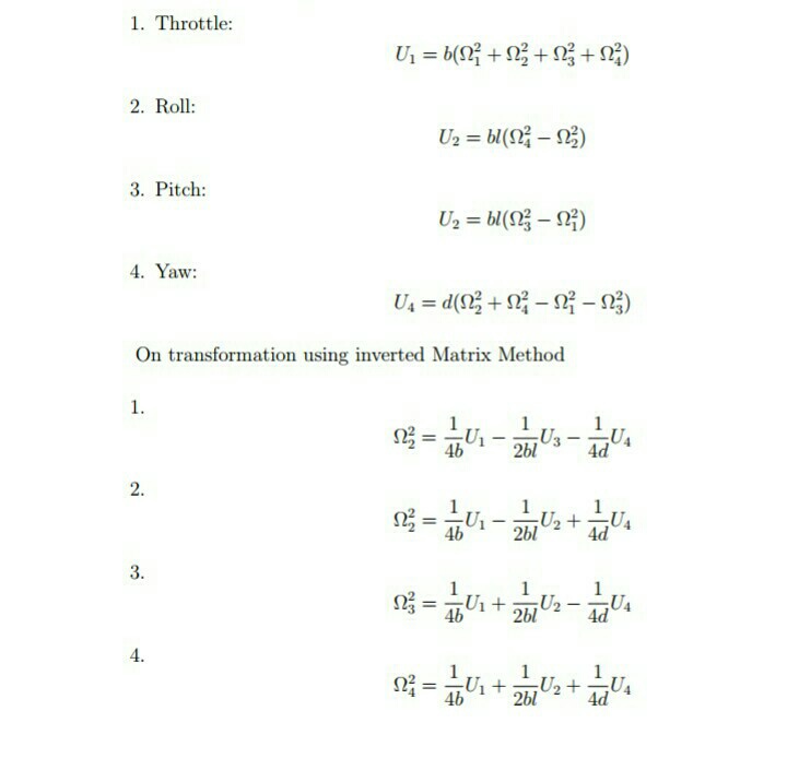
Flight Dynamics
Four Inputs
- U1 → Affects Altitude
- U2 → Affects a Rotation in Roll Angles
- U3 → Affects Pitch Angle
- U4 → Affects Yaw Angle
Six Output States
X, Y, Z, Θ(Roll), Ψ(P itch), Φ(Y aw)
Overall Propeller Speed
Modules
Kinematics
Right now we have raw gyroscope data and raw accelerometer data, but neither one of
these sensor outputs give us an accurate enough estimate to be used in our stabilisation algorithm.
What we will do, is combine accelerometer and gyroscope outputs via complementary filters. Output from our kinematics will feature strongly suppressed noise from the
accelerometer along with the gyroscope output without the ”drift”.
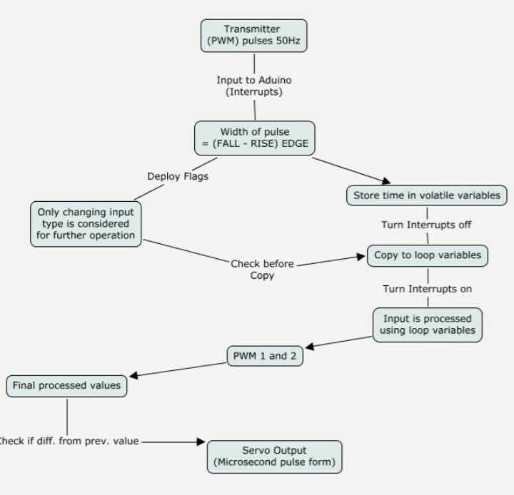
Receiver-Transmitter
Obtaining Signal from Receiver
This algorithm along is illustrated in the flow chart:
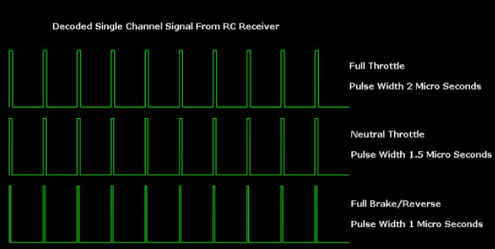
Servos
The output from Transmitter is of PWM format where the length of pulse width
determines the power output to the motors (shown in figure[7]).
The motors are powered through the ESCs using PWM signal which can be generated
from the Arduino board using the Servo library. A servo expects a pulse of between 1 and 2 milliseconds to be sent about every 20 milliseconds. We need to measure the width of input pulses from the receiver using interrupts along with the PinchangeInt library [10]. Reasons for choosing this library are enumerated
as:
- By using the conventional functions like pulseln() or normal interrupts. We need to stop receiving signals from the transmitter for at least 2 milli second duration and thus, we have wasted computational power equivalent to 32,000 operations on an Arduino.
- Provides individual interrupt handler functions for up to 21 external interrupts and we are able to use the timer function directly in the interrupt block
- It provides the additional functionality of pin number and state to be available for access inside the interrupt handler
- The Servo library for the Arduino UNO can be used for controlling up to 12 Servos at a time on a single Arduino UNO.
OUTPUT TO SERVOS
We have to take into accont the following precautions before giving output to servo
motors:
- Shared variables are updated by the ISR and read by loop. Before execution of the main programme loop we must immediately take local copies so that the ISR can keep ownership of the shared ones and stop the interrupts2 during this copying process and immediately switch them back on so we are able to receive new signals.
- Shared variables should be kept volatile because they are used both in main loop
and ISR. The local values can be kept static and only they should be used in main code processing. 3 - Updating a servo output continuously can consume system time and power so, we have deployed appropriate flags at transmitter inputs which change only when the incoming input varies. Thus only the changed input values are copied to servos (or used for processing in the main code)
- The copying of the inputs to the servos will consume system time. So, we will only start copying when the relevant input is given and rest of the time the copying is stopped. This will increase the system efficiency manifold.
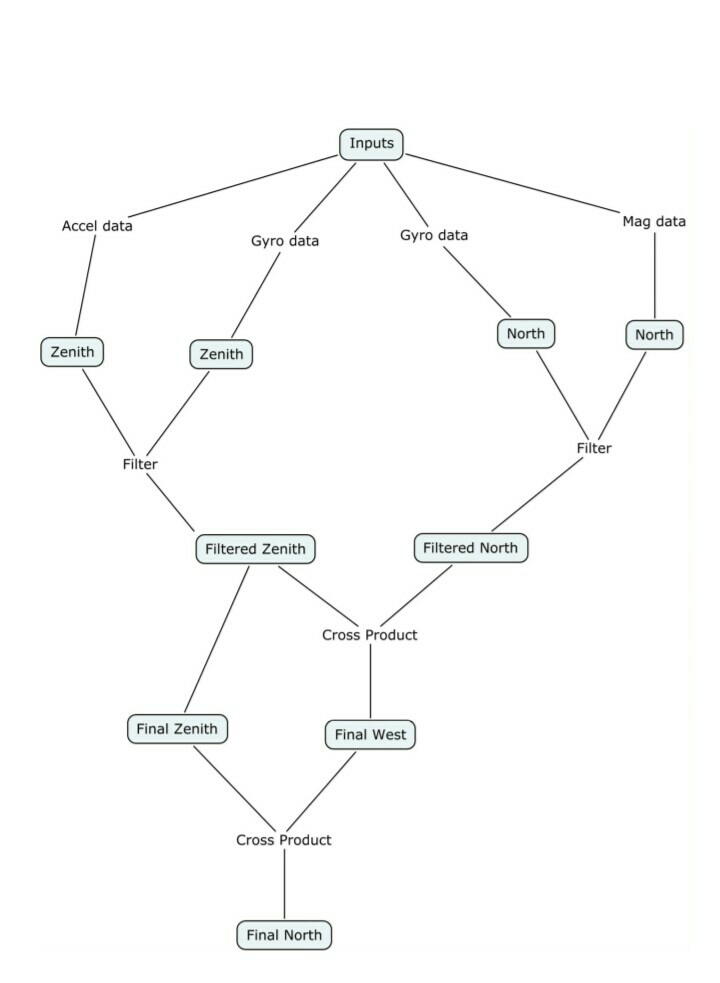
FILTER
Converting the data to angles and filtering
We set a global frame comprising of the magnetic North, West and Zenith as the 3 axes.
This is illustrated below
Inputs to this block
- Magnetometer
Provides the 3 element vector giving the (x, y, z) coordinates of global North in the body frame - Accelerometer
3 element vector giving the (x,y,z) components of the acceleration in the body frame with the assumption that when hovering the reading is +g along z. - Gyroscope
Angular velocity components (x,y,z) of the rotation of the global frame as viewed in body frame.
Important Functions
- Obtain North from magnetometer North is obtained directly from magnetometer input reading
- Obtain Zenith from accelerometer : To obtain Zenith we make the assumption that the quadcopter acceleration is always along the body ‘z’. Thus any components along the ‘x’ and ‘y’ axes are due to gravity and this enables us to obtain the orientation of the vertical (Zenith) of the global frame.
- Obtain North from gyroscope
We know the angular velocity of the zenith in the body frame. This can be used to obtain the x, y and z velocities of the Zenith vector in the body frame. Integrating this one can obtain the coordinates of the zenith vector in the body frame. - Obtain West from gyroscope
Follow the exact same procedure as above - Obtain Thurst
Subtracting out the gravity vector from the vector formed by the accelerometer
data, one can get the thrust acting along the body ‘z’ axis. - Filter the data
We use a simple complimentary filter which is a weighted average of the two inputs. We use it to filter the north obtained from the gyroscope and from the magnetometer as well as the zenith obtained from the accelerometer and the gyroscope. - Obtain West
This is done by simply taking a cross product of the filtered North and Zenith directions. - Correct North
It may be possible that our North, West and Zenith may not be perfectly orthogonal. So we recalculate the North direction by taking a cross product of West and Zenith. At this point we have obtained the axes of the global frame in the body frame. The next step is to normalize all the vectors.
We then note that one can body ‘z’ axis by taking the ‘z’ components of the above obtained North, West and Zenith vectors and similarly for the other body axes. - Get the pitch angle
- Get the roll angle
This algorithm along is illustrated in the flow chart
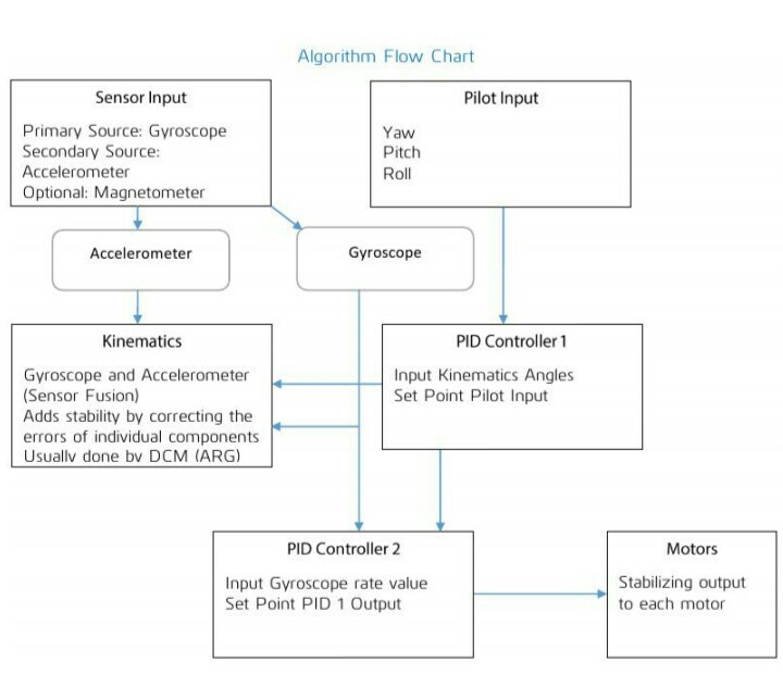
First PID
From the diagram below you can see that our first PID controller will take output from our pilot as ”Set Point” and kinematics (containing current estimation of yaw, pitch and roll angles) as input. Output from our first PID controller will contain the angle desired by pilot +- current kinematics angle. This acts like an ”accelerant” for the second PID. In this case ”accelerant” means that the value from our first PID controller will
determine how ”fast” we want to correct for the current stabilisation error. We are directly controlling Thrust and Yaw angular velocity but for pitch and roll we need to have a control on angle as piloting by giving angular velocity is a very difficult. To do this we implement control of roll and pitch in two steps.
There are two PID loops running here:
- Roll (angle) PID
Input – Roll angle from filter
Setpoint – Roll angle from Receiver
Output – Setpoint for Roll(velocity) PID - Pitch (angle) PID
Input – Pitch angle from filter
Setpoint – Pitch angle from Receiver
Output – Setpoint for Pitch(velocity) PID
Second PID
The second PID controller takes the ”accelerant” from the first PID and Receiver as ”Set Point” and current gyroscope output (gyro Rate) and Thrust from filter as input.
The resulting output from the second PID controller is the decimal value representing
force that has to be applied to each of the axes to correct for the stabilisation error.
In our case this force is generated by spinning propellers, and can be controlled by adjusting the speed of the rotating propellers.
There are four PID running controlling one degree of freedom each.
- Roll (velocity) PID
Input – Roll velocity from Gyroscope
Setpoint – Output of Roll(angle) PID
Output – U2 (PID sum controlling Roll) - Pitch (Velocity) PID
Input – Pitch velocity from Gyroscope
Setpoint – Output of Pitch(angle) PID
Output – U3 (PID sum controlling Pitch) - Thrust PID
Input – Thrust from Filter
Setpoint – Thrust from receiver
Output – U1 (PID sum controlling Thrust) - Yaw (velocity) PID
Input – Yaw velocity from Gyroscope
Setpoint – Yaw angular velocity from Receiver
Output – U4 (PID sum controlling Yaw)
COST ESTIMATION:
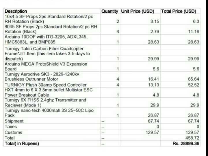
Kindly,follow http://www.alexandriafranklins360technology.tech.blog for more updates.

